Tuesday, January 09, 2007

LCD Screen prototype - finished!

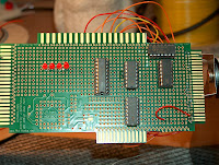
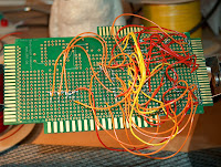
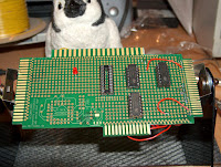
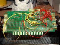
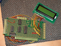
Well, I think I've taken this as far as I need to, the final prototype board is shown here, and yes...it could be a lot simpler, and yes... it could be packaged up into a nice box, but that was never the plan. The mass of wires at the back show just how much even a simple project needs and I've learnt several valuable lessons/tricks while doing this so its been a good 1st project.

Given access to a GAL I guess it would only have been a couple of chips, and I could probably have decoded the addresses down to a single location rather than a bank of 128! But thats unimportant really.
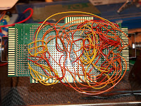
I've never been terribly good at soldering, but I'm definitely getting better at it; practice makes perfect I guess. Although having bought a proper wire stripper I'm amazed just have vital it is! I've always just done it by hand which usually means a long chunk taken off. But with these, I can snip the plastic off a small end of the wire and using a big magnifier, solder it on easily. Its also SO quick to strip a wire, something I just didn't realise! I'd hate to have done this board's wire strippng by hand.
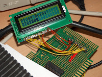
The last image here shows the screen hard at work printing a counter and a welcome message. The code to do this is tiny - and I'll post it later for any who are curious - and extremely easy to use. I may not scrap the board just yet, it may even come in hand for debugging! Printing a row of text will take around 32 scanlines - mainly because I have a fixed delay and have to take into account that I might be in FAST mode. But for debug text...32 lines is okay.

So with this finished, I now need to wait on my SRAM+GAL's (which are finally on its way I think!) and I can look to doing a brand new external RAM card for the Plus/4, or perhaps the MMC card which would be much more interesting I guess. Although...Xeo3 is starting to beg for some attention, so I might dabble a bit in there soon.

All that said... the very 1st thing Im doing next is a board from the expansion bus that can connect to a breadboard. This would have been much easier on a breadboard!

Edit: Okay, code can be found HERE!. Its not terribly exciting, but it completes the project (until I get around to making a circuit diagram that is...)

Sunday, January 07, 2007

Plus/4 LCD addon!!!

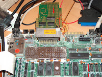
COOL!!! My first proper hardware add on! I've connected up the remaining lines, added some power and wrote a little test program to initilaise it, and then print to it and hay presto! A little LCD screen add-on!

Of course...Its not that easy. I've missed out a lot of stuff here. For proper full speed access I need to be able to read the busy line which requires READ access. This in turn requires another buffer (I think), and some more logic to detect the READ line and then setting the datalines (at least 1 bit) to be the values it needs to be. All I've done just now is put in some big delays so I know the text will have been set.

Although...after playing a little...it looks like the Plus/4 is so slow.... the delays can more or less be taken out! Which is pretty cool...Still, its not "right", but it does work. I also have no way to reset it properly just now, which means I'd have to add some rest circuitry.

But aside from this...I don't care! It works! Its really easy to write to! And its cool!!!

Saturday, January 06, 2007

Memory mapped LED's!!

What a fun night I've had! I've expanded my little test board to now have 4 LED's, but now I've also added a single byte of write only memory via the 72LS373 chip. This means that when I poke 1, the first led lights up, 2 the second, 3 1 and 2 and so on! So cool! You can't really see on the picture, but theres 2 LED's on and 2 LED's off. I did this simply by typing "POKE 65024,10" in BASIC. Now, I know this could be done via the userport, but 8 couldn't! And this is the basic stuff I need to be able to add lots of cool stuff!.

When I finally get my RAM, I hope to try and add external memory using basically the same idea, and having a RAM bank register just like this! I'm NOT looking forward to wiring the thing up though!

I had a few problems adding this to the old design though. First was again a simple case of not fully checking the IC pinouts, it really does get tricky when the IC is upside down and back to front! But there was also the problem of the 6502 using a 2 phase clock, which meant I had to check that line as well as the R/W line before latching the data, and that the Write line was basically inverted from what I though it should have been - bit of a pain that. So I had to add another chip, this time a proper AND chip (I got some yesterday from a Maplin store). I also had to figure out how to use the 373 chip as a normal latch to store my data, which meant building a new mini breadboard circuit to try things out on. However, once I figured it all out, I was able to turn my LED's on and off via a memory location in the I/O space. Oh! And whoever wrote the little IO text file describing whats where - THANKS! Helped loads!!

So...whats next! I guess add the other 4 data lines so I have a full byte there, and then perhaps hook up the LCD screen to it and play with having the Plus/4 drive it! Although, after all of tonights work, that should be easy - the data's there, its just a matter of soldering it all into place. I wonder how hard a SID chip add on would be to build, or a memory mapped MMC card. Once you've done this, the rest should be easy - although, I've not done memory reading yet, this is a write only register.

I'd also just like to point out to anyone that would like to try this kind of thing, that I've only just started doing electronics - just a couple of months really, and once you get past all the resistors and other do-hickys, its all pretty simple. Hooking up chips is really easy, particually out the back of a retro computer! Anyway, if you really fancy learning, I'd highly recomend Electronics for Dummies (ISBN 0-7645-7660-7), which is the main book that got me started, and The BLACK ART of Video Game Console Design(ISBN 0-672-32820-8), which has lots of info on how basic computers work. This book is part of the XGameStation setup, which is also fab. Its a little heavy going at the start delving into areas you just don't need to know about, but the information past that is invaluable!

Although...a small word of warning - it ain't cheap to start! Parts are pretty cheap, $0.30 for a cheap here, $0.95 for a PIC there, but you really need a small stash of things, and these add up really quickly! And don't get me started about if you want to make your own boards!!

Friday, January 05, 2007

My First Baby!


Well, I've been busy playing with my logic chips and an 8bitbaby (which is a generic retro interface card) and the Plus/4. I'm currently trying to map a small range of I/O addresses ($FE00-$FE7F) to a LED.

That is, whenever this address range is accessed, the LED should light up - in theory anyway.
After fixing it several times - mainly because the IC diagrams were confusing, particually as I was wiring the thing upside down! I'm getting more and more respect for folk that have been doing this for years, it takes a really steady hand and serious dedication as you have to quadruple check things to make sure its all working! (not to mention follow messy wires all over the place)

This is my first real attempt at actually building a whole circut that I've designed, away from a breadboard and its taken ages! I think what I really need to do is build an interface that I can hook-up to a breadboard; things will go a lot faster if Im not soldering all the damn time!

However, all that said, it does actually work! If the program hits locations $FE00 to $FE7F, the LED comes on!! How cool is that!
This is the reason I wanted to learn electronics in the first place, so I could build cool little add-on's. Now I know a memory mapped LED isn't exactly exciting, but if I add an octal flip-flop (which gives me 1 byte of memory) and enable it on write access, I can then use this to drive the LCD screen! This means I could have a memory mapped LCD screen expansion card! Now that is cool!!

Oh...and I also see why people use GAL's everywhere now; they are ideal for this kind of thing! I have a couple ordered, but no sign yet..... and although my EPROM programmer can write to them, I have no software that builds the binary file TO write to it?!?!?! So I've not a clue how to physically use them yet! This image shows the logic I've used... which is also why its a bit ugly. I guess I could use an EPROM instead of a GAL for now....

Edit: Oh...and looking at that diagram, yes...I really need to get some basic AND and OR gates!

Thursday, January 04, 2007

PIC fun...

I got my logic chips today, but no sign of the SRAM, so I'm still playing with my little screen. I've fixed the last of the buglets so I can now use it properly; I even got the backlight working properly! The PIC only has 2K of ROM on it so I'm kind of limited, but its a good learning experiance. One thing I did get today are a stack of voltage regulators, so I can stop using the 2 resistors and use the IC instead.

I also got a few 3.3V regulators which I can now use to play with the MMC socket on the C64 or plus/4 userport. With the EPROM, and logic chips, I guess I could play with proper code, but thats a helish way to develop. Your better having RAM there. The Plus/4 is easier to code for since the download is now in ROM and its pretty quick to squirt a few bytes over, but the user port on the Plus/4 is split into 4out 4in, whereas the C64's has 8 bi-directional bits - and a couple of other lines besides.

Anyway, I think I'll probably play with the MMC or my giant LED panels next - until I get my SRAM that is....I could always hook up the LCD panel to the plus/4 I suppose, have a single memory location that maps out to the wires or something. Ahh...so much to do, so little time...

Wednesday, January 03, 2007

Holidays...

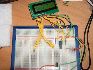
Ah well, my holidays almost over, couple of days left now. *sniff* Still, at least Im finally getting a couple of days to actually play with stuff. I hooked up a little LCD screen to one of my 16F628A pic's. It took a little longer than I thought, but I managed to get it initialised and speaking to it. I was being silly and forgetting that one of the instructions wanted a bit number, not the bit value (so 0 to 7, and not 1,2,4,8 etc.) DOH!

Oh well, looks neat - nice little flashing cursor and everything!

On a more Plus/4 related topic...I should get some logic chips tomorrow (NANDs, NORs etc.) and a couple of static RAM chips so I'm itching to have a crack at trying out that hack I thought of to add more RAM via the expansion port. I really have NO idea if its going to work since people like Solder (who's been doing this stuff for years!) says you can't do it, but I'm being optimistic and assuming that I'm thinking as a software coder who uses hardware the way hardware guys never think of. I'm pretty sure as long as the expansion lines do what I think, I should be able to add lots of banked RAM as an external BOX without any mod's internally. If I can, then a full on, RAM+SID+MMC should be possible...man, that would be cool.

Anyway....until I get these logic glue chips, I can't do very much - although I did get a hacksaw so I can cut my 8bitbabys down to size! Stupid things.

I wonder if I can use a Plus/4 keybaord with a PIC....Mmmm...I could have it type on the little screen!

Sunday, December 31, 2006

Last code of 2006...

*sniff* There goes another year, man do I feel old now. Well, almost...couple of hours left I guess.

I've just updated my uploader ROM to fix some minor issues, and to add a loading bar. Its great to have programming space to burn! When I was coding it, I kept it as small as possible so that anyone typing it in by hand didn't have too much to do. But now its on ROM and doesn't even have to fit in the small space I'd use before, I can splurge on visuals a bit. Nothing too much, just the loading bar from the C64 one. I might add more features later on. I was also testing my new EPROM UV eraser which I guess works fine as the new code went on easily enough.

I hope to get a couple of 16K EPROM's soon and I'll put OS96 on it so I can do some stuff for Solder.

Lets hope we have as much fun next year as we did this, it looks like being a very busy one for me at work, so I hope I can find the time to finish XeO3 - I think 2007 could be the year!! Have a great new year peeps!

Saturday, December 30, 2006

Stupid, Stupid, Stupid....

Yep...just realised I've been stupid. Theres no need to make a "userport" addon to expose more lines for ROM selection as I can just add a new hardware register(s) that do anything I want. idiot. This is in fact what Solder did on his 1Mb ROM expansion.

I wonder if you could add RAM instead of ROM and just write to it and page in in/out.... I know that writes fall through to the RAM under it, but if it could write to both, than while you'd lose 32k of RAM under the ROM (or rather pretend ROM as its now RAM), but gain megabytes of parged RAM for doing whatever you like....I wonder.. I suspect someone with a bit more skill would have to try that.

I think the 1st thing I'll do as an add-on, is a new register that sets some LED's, this is the basis of everything you add on a computer really, so it should be pretty good fun.

(Oh...and whoever designed the "8bit baby" has never plugged one of them into a Plus/4 in their life!)

Friday, December 29, 2006

Plus/4 hardware fun.


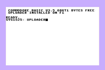
I've having a bit of fun making my first ROM for the Plus/4, nothing too amazing but getting used to developing and burning ROM's for it. I've put my uploader onto ROM so that I don't have to load it from disk anymore and for a first attempt, its almost there. I altered minus4w so that I can autoload a ROM as well as a program so that I can test it better; although being an uploader, I can only test it so far inside an emulator!

I removed the 3-plus-1 ROM's from my development machine and put in an 8K EPROM (the slot's designed for 16K eproms, but 8K works just fine), and I now get the screen shown. I pinched the start-up code from the 3-plus-1 ROM's as its pretty handy, and I'll release it as source later on. Using this stuff, I could build a complete debug system on ROM meaning I leave virtually all the RAM for a game/application, which would be very cool.

I was also thinking about XeO3 and wondering if I could put it on a ROM, and I could...but it would be a little odd. I suspect that I'd need more than the available ROM slots left, so I'd need to have a cartridge and a connector from that into the userport so that I can expose a couple more control lines and page more ROM's in/out (probably allowing up to a 512k ROM), but that would mean that I could do a version of XeO3 completely ROM driven - no loading times! How cool would that be!

I also still want to try and make an MMC interface at somepoint and have a ROM bootup and load a basic filemanager fom the MMC card. This again means that there would be basic loading on ROM and you could put games etc. on an MMC rather than ROM/DISK. However, since this would take over the expansion port, you really need a SID card on there as well....bummer. The SID interface doesn't look too hard though, so you never know.

Anyways....I'll release all this stuff as soon as it's in a fit state - getting tools on ROM is pretty neat, particually since the Plus/4 has 2 available ROM slots internally - which I do really like.

Monday, December 25, 2006

Merry Christmas!!!!


God bless you all, and I hope everyone has a great day!