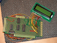
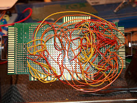
 Well, I think I've taken this as far as I need to, the final prototype board is shown here, and yes...it could be a lot simpler, and yes... it could be packaged up into a nice box, but that was never the plan. The mass of wires at the back show just how much even a simple project needs and I've learnt several valuable lessons/tricks while doing this so its been a good 1st project.
Given access to a GAL I guess it would only have been a couple of chips, and I could probably have decoded the addresses down to a single location rather than a bank of 128! But thats unimportant really.

I've never been terribly good at soldering, but I'm definitely getting better at it; practice makes perfect I guess. Although having bought a proper wire stripper I'm amazed just have vital it is! I've always just done it by hand which usually means a long chunk taken off. But with these, I can snip the plastic off a small end of the wire and using a big magnifier, solder it on easily. Its also SO quick to strip a wire, something I just didn't realise! I'd hate to have done this board's wire strippng by hand.
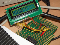
 The last image here shows the screen hard at work printing a counter and a welcome message. The code to do this is tiny - and I'll post it later for any who are curious - and extremely easy to use. I may not scrap the board just yet, it may even come in hand for debugging! Printing a row of text will take around 32 scanlines - mainly because I have a fixed delay and have to take into account that I might be in FAST mode. But for debug text...32 lines is okay.
So with this finished, I now need to wait on my SRAM+GAL's (which are finally on its way I think!) and I can look to doing a brand new external RAM card for the Plus/4, or perhaps the MMC card which would be much more interesting I guess. Although...Xeo3 is starting to beg for some attention, so I might dabble a bit in there soon.
All that said... the very 1st thing Im doing next is a board from the expansion bus that can connect to a breadboard. This would have been much easier on a breadboard!
Edit: Okay, code can be found HERE!. Its not terribly exciting, but it completes the project (until I get around to making a circuit diagram that is...)
No comments:
Post a Comment