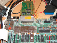
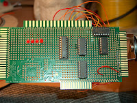
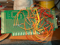
 What a fun night I've had! I've expanded my little test board to now have 4 LED's, but now I've also added a single byte of write only memory via the 72LS373 chip. This means that when I poke 1, the first led lights up, 2 the second, 3 1 and 2 and so on! So cool! You can't really see on the picture, but theres 2 LED's on and 2 LED's off. I did this simply by typing "POKE 65024,10" in BASIC. Now, I know this could be done via the userport, but 8 couldn't! And this is the basic stuff I need to be able to add lots of cool stuff!.
When I finally get my RAM, I hope to try and add external memory using basically the same idea, and having a RAM bank register just like this! I'm NOT looking forward to wiring the thing up though!
 I had a few problems adding this to the old design though. First was again a simple case of not fully checking the IC pinouts, it really does get tricky when the IC is upside down and back to front! But there was also the problem of the 6502 using a 2 phase clock, which meant I had to check that line as well as the R/W line before latching the data, and that the Write line was basically inverted from what I though it should have been - bit of a pain that. So I had to add another chip, this time a proper AND chip (I got some yesterday from a Maplin store). I also had to figure out how to use the 373 chip as a normal latch to store my data, which meant building a new mini breadboard circuit to try things out on. However, once I figured it all out, I was able to turn my LED's on and off via a memory location in the I/O space. Oh! And whoever wrote the little IO text file describing whats where - THANKS! Helped loads!!
So...whats next! I guess add the other 4 data lines so I have a full byte there, and then perhaps hook up the LCD screen to it and play with having the Plus/4 drive it! Although, after all of tonights work, that should be easy - the data's there, its just a matter of soldering it all into place. I wonder how hard a SID chip add on would be to build, or a memory mapped MMC card. Once you've done this, the rest should be easy - although, I've not done memory reading yet, this is a write only register.
 I'd also just like to point out to anyone that would like to try this kind of thing, that I've only just started doing electronics - just a couple of months really, and once you get past all the resistors and other do-hickys, its all pretty simple. Hooking up chips is really easy, particually out the back of a retro computer! Anyway, if you really fancy learning, I'd highly recomend Electronics for Dummies (ISBN 0-7645-7660-7), which is the main book that got me started, and The BLACK ART of Video Game Console Design(ISBN 0-672-32820-8), which has lots of info on how basic computers work. This book is part of the XGameStation setup, which is also fab. Its a little heavy going at the start delving into areas you just don't need to know about, but the information past that is invaluable!
Although...a small word of warning - it ain't cheap to start! Parts are pretty cheap, $0.30 for a cheap here, $0.95 for a PIC there, but you really need a small stash of things, and these add up really quickly! And don't get me started about if you want to make your own boards!!
7 comments:
Hi Mike!
Could you please clarify what this "there are only four out lines on the User Port" is? You mentioned this now the second time. I'm sure that i saw in some book one example about driving a parallel port printer and another one about an 8 channel intrusion detector implemented through the User Port.
I think you are talking about only the ACIA (6551 - mapped at $FD0x) and forgot that there is also a 6529B (mapped at $FD1x) connected to the port. The latter is an 8 bit parallel bi-directional port. AFAIK paralellized 1541s work on plus/4 also via this.
Best regards,
gerliczer
Yes there are a few others tied to the RS232 part I think, but I have no information about using them.
I'm comparing to the C64 which has a proper bidirection port that you can toggle with a data direction register. As far as I know, the Plus/4 doesn't have one of these and seems to be fixed to 4 out 4 in. However.... I have VERY little info on these ports, so I could be WAY off.
This is about all I can find.
http://solder.dyndns.info/pub/files/commodore/plus4/hardware/Service_Manual/17_Userport.pdf
You should try to find someone having this book: http://plus4.emucamp.com/publications.php?pid=400062 or its original: http://plus4.emucamp.com/publications.php?pid=400063 . This is where i read the mentioned examples. Maybe he/she can translate and send you the relevant pages.
gerliczer
Had a look through the code....
I currently use $fd01/$fd02 for flags (to/from the PC).
and $FD10 for 8 bit data transfer - however, the bits appear to be hiredwired to 4out/4in Im looking at the ANCO ref manual, and it doesn't appear to have anything about a data direction register.
This means theres only 4 outputs on the +4 parallel port....unless you can find a DDR somewhere... :(
Hi Mike!
If the parallel port lines are not bidirectional on your plus/4 then i think the 6529 driving it is broken. I checked on various sites that there are no components between the User Port connector and the 6529, and since the keyboard is read through a 6529 too it must be bidirectional on all its lines.
Yep, I know that...and I agree. But without a register to enable you to change it, it doesn't matter! I think its setup like that by default either in the ROM or on the CHIP itself.
If the ROM sets it, then yes...once we find the register we can change it...but until then, its fix at 4in, 4 out....
Mike!
The userport is bidirectional 8 bits. Only the incoming and outgoing values are AND-ed together. So before you want to read an incoming line you should put a 1 bit there. For example if you want to read on all 8 bits, you should put $ff to $fd10 before reading. On write you can write anything for all of the 8 bits and they can be read on the other end.
I use my parallel 1541 and a HP LaserJet printer this way.
Regards, Siz
Post a Comment