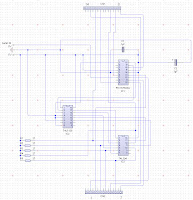
 So...I've decided to build the small scale prototype so I can take it into work and see what its like - if its bright enough, and readable etc. So I've made a circuit diagram of the previous version so that I can make up a larger board (shown left).
After doing that, I rebuilt the circuit from scratch using the diagram to verify that it does work before I solder 1,000,000 wires wrongly! Because I now have a spare transmit wire on each unit, Im going to forward the packets form the master to each slave which in turn saves me from giving each an ID.
 I'm not really looking forward to soldering all these wires, but I suspect its a good idea before I go and order a stack of custom circut boards fomr one of these on-line places. So, after building it, it looks like the diagram is correct and I can now start wiring it all up to a larger prototype board. I picked up some new larger boards for trying this stuff out on with space for 5 panels, and a little space at the end for the controller. I cand then use this to test all the code I'll need to write for the PC comm's as well which is pretty good.
 I've started by laying out the connectors and DILL's ready for the wires, so now I need to start wiring on the reverse side. Once I get the new demultiplexor chip, I'll replace one of the panels with the new chip to check it works okay (although I'll try it on the breadboard version first of course).
SO, it'll prbably take me most of this week to solder up the board, but I still need to add the new comm's forwarding from panel to panel which I'll do once the board is complete - as its a minor change.
No comments:
Post a Comment