Looks like Csabo has put a link to the Xeo3 video on to a new site which has generated a few comments; some good ones....
Check it out here: digg.com
Friday, February 09, 2007
Monday, February 05, 2007
Scrolly message impass...
Damn....My new 4028 chips arrived at the weekend (the BCD to Decimal ones), and I got all excited and rewired my breadboard prototype to try it out. Once it was all wired up, I switched it on and....bugger....didnt work.... I spent the next day or so trying to figure out why!
Here's which I think is going wrong... The old chips had a LOW TTL level output of around .6volts, where as these actually output 0volts. The problem being, that since I use pull up resisters to increase the brightness I need some sort of voltage there so that the power from the pullup doesn't power the LCD matrix when I dont want it to. But with 0volts, the pull up supplies power to both. Damn.
So, next thing to try is a few transistors, although Im almost at the point where I'm thinking sod the extra expense... get the slightly larger PIC (which will probably cost about 50-60pence more per unit, but save power, complexity and wiring - it almost has to be worth it.
Thursday, February 01, 2007
Plus/4 flash ROM
I was going to put OS96 on some EPROM's so that I could do some bits for Solder, when he suggested that I get a larger ROM and use a switch to toggle back and forth. After thinking about it for a little, I decided to go one step further and put in a single 128K FLASH ROM. This needs a larger socket, a NOR gate and a switch, but will allow me to update the ROM with a little more ease than EPROM's.
I guess I could allow the Plus/4 itself to reprogram it, but I think that might be taking it too far as no one else but me will be using it, and I have a lovely EPROM/FLASHROM programmer. It will mean I could have 4 different ROM's on here if I wanted though - although only 2 are needed just now....but you never know!
I guess I could allow the Plus/4 itself to reprogram it, but I think that might be taking it too far as no one else but me will be using it, and I have a lovely EPROM/FLASHROM programmer. It will mean I could have 4 different ROM's on here if I wanted though - although only 2 are needed just now....but you never know!
Sunday, January 28, 2007
Making tracks....
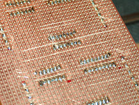 Damn.... So much for starting to solder the first batch of wires tonight! I'd forgotten that using a stripped board meant I had to go and cut all the tracks so that the chips wouldn't short each other out! I then had to go and verify all the cuts with a voltmeter to make sure they really were cut! Oh well, I guess I'll start the fun and games tomorrow.
More scrolly messages
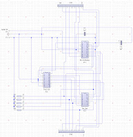 So...I've decided to build the small scale prototype so I can take it into work and see what its like - if its bright enough, and readable etc. So I've made a circuit diagram of the previous version so that I can make up a larger board (shown left).
After doing that, I rebuilt the circuit from scratch using the diagram to verify that it does work before I solder 1,000,000 wires wrongly! Because I now have a spare transmit wire on each unit, Im going to forward the packets form the master to each slave which in turn saves me from giving each an ID.
 I'm not really looking forward to soldering all these wires, but I suspect its a good idea before I go and order a stack of custom circut boards fomr one of these on-line places. So, after building it, it looks like the diagram is correct and I can now start wiring it all up to a larger prototype board. I picked up some new larger boards for trying this stuff out on with space for 5 panels, and a little space at the end for the controller. I cand then use this to test all the code I'll need to write for the PC comm's as well which is pretty good.
 I've started by laying out the connectors and DILL's ready for the wires, so now I need to start wiring on the reverse side. Once I get the new demultiplexor chip, I'll replace one of the panels with the new chip to check it works okay (although I'll try it on the breadboard version first of course).
SO, it'll prbably take me most of this week to solder up the board, but I still need to add the new comm's forwarding from panel to panel which I'll do once the board is complete - as its a minor change.
Tuesday, January 23, 2007
Scrolly messages.....
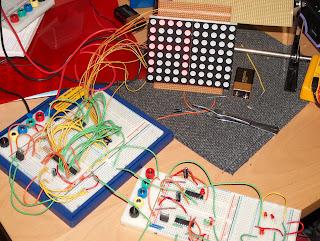 So.... I've managed to get a control PIC sending data via a serial connection to the display PIC, which recieves the data under interrupt and displays it; but only IF the packet is for that segment. Follow that? This is basically the control needed for my scrolling message board and appears to work fine; but disaster! You cant appear to have input serial only! Which means by enabling serial, I lose 2 output lines! AAAArrrrghhhhh!!!
This has forced me to multiplex some lines and currently I need 2 chips to do this. a 3 to 8 demultiplexor, and an invertor. The demultilexor outputs inverted lines so for now I need an invertor, but I can use a 4028 BCD to decimal decoder which doesn't appear to require this - and its reasonably cheap. It's either this or use a PIC with more control lines, but that costs double at just over £2 per PIC, rather than $0.30 more. The 8bit serial to parallel shift register that was suggested earlier would also work, but is more expensive at $0.49, although it is more versitile and could free up lots of lines, but I don't appear to require that so I'll probably plump for the cheaper option.
I've also started coding my PIC's in "C", and things are moving much quicker than using assembler. Its also interesting to see just how much code you get for 2K space. If I was really stuck, I could drop down to ASM again, but so far "C" is working out great and does all the really tricky stuff for me without having to worry about it.
So, what I currently have is a scrolling bitmap through a single matrix unit. I'll build perhaps a 5 unit module with a message/bitmap scrolling over this and then take it into work to test lighting etc. and see how its going to look. After that, I'll need to start looking at getting actual boards made up so I can produce a fair number of them.
I also fixed my USB experimenter box so that it outputs reasonable voltages, so I'll use that to control it, getting the master PIC to do the comms and send on any data the PC sends. Being USB it should be pretty quick and if needs be, you can have 4 of them connected at once.
Sunday, January 14, 2007
Plus4 memory
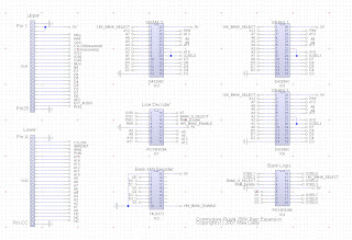 Ever since my static RAM arrived I've been toying with how to do the Plus4 RAM expansion, and after yesterdays revalation about using PIC's as decoders, I think I've hit on a nice way of doing it. The piccy shown is the current design which also has the advantage of being pretty cheap (well...as much as it can be). While PIC's are CPU's, the 16F628A is only around £1, which is still cheaper than all the logic chips I was using to just decode the address lines last time and while I could probably lose a chip from that, its still cheaper and can be upgraded due to the fact its programable. The only thing Im not sure about is if the program running will test/set the lines quick enough. Its 4Mhz by default, but you can ramp it up to 20Mhz if you need to, but as I currently use all the control lines, I can't do that. I could buy a larger PIC (for £2) and then have plenty of space for this stuff, but I've a stack of these so I'll see how it goes first.
This design allows for 16, 16K banks of RAM located at $8000 although bank 0 will also reside at $c000->$ffff. Its kind of like a Spectrum 128 deisgn I guess, where you have a single area that can page in lots of banks of RAM. However, theres still the 32K of RAM from $0000->$7fff where you can copy stuff around if you need to. The normal RAM from $8000->$ffff will just be rubbish (more or less) as its written to at the same time as the expansion, but that shouldn't matter.
You probably won't be able to put character sets etc. there (as I have no idea what will happen when it "banks", but any other kinds of data should be fine...I think. This is all guess work at the moment and I still have no idea if this will actually work...but its worth a try as all current memory expansions require you to solder onto you Plus/4 motherboard!
Saturday, January 13, 2007
More hardware fun!
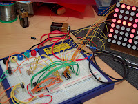 I'm about to start making a large LED scrolling message board for work so we can dump build messages/alerts to it. We look at how much they would cost to buy, but for the size we were looking at the prices ran into the thousands! Which is just a bit silly.... We also need to be able to get a our own programs to be able to talk to it, which isn't what you get from the cheaper models. So I thought I could probably manage to build one cheaper; quite a bit cheaper! I got a stack of the LED matrix panels in so I started playing with them and figuring out how they work. This is actually my second attempt, the first worked fine but was a little dull. So now I have a 5V pull-up line to help keep the brightness up. Unfortunatly, they will never be as bright as a 5x8 array of LED's could be since you have to scan these (put on 1 row or column at a time) due to the pin/matrix effet. Still, they use a fraction of the power so thats always good and if I place a sheet or transparent red plastic (or red anything) over it, it makes it looks even brighter so it should work out fine.
I'm using a PIC16F628A to drive it, but Im running low on lines as it takes 13 to drive it directly, and I still have to get some COMM's in there to be able to talk to it. I originally used a 3 to 8 demultiplexor when I used to scan 5 pixels of 8 rows (scanning downwards), but I swapped that to scan 8 vertical pixels of 5 colums. This has helped to keep it a little brighter as the LED's aren't off for as long, but its really screwed using the 74LS138 as it outputs inverted lines and I can't use that without an invertor chip...3 chips to do a 1 chip job...Oh well, I'll see how I get on, I might manage - I still have 2 lines left, although I've had trouble with one of them before.
Oh...and on the Plus/4 LCD screen front, I also figured I could ditch all the logic chips I had and use a PIC instead...after all, its just a set of control lines going in and a 0 or 1 being set on an out going line if the condition are met...a PIC could do that in its sleep! That would get the +4 LCD down to 2 chips...I could replace the buffer chip with another PIC and that would let me return data easily, AND have even MORE actual RAM there by using the PIC's memory.... handy little thing PIC's... I'm also amazed at how people doing hardware have so many unexpected options, EPROMS or PICs being used as logic decoders... or even the 74LS138 (3 to 8 line demultiplexor) which can also be used a logic decoder... As long as you remember its lines in->lines out...then you have a whole HEAP of things you can do.
Tuesday, January 09, 2007
LCD Screen prototype - finished!
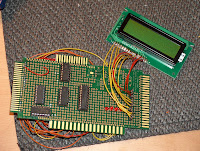 Well, I think I've taken this as far as I need to, the final prototype board is shown here, and yes...it could be a lot simpler, and yes... it could be packaged up into a nice box, but that was never the plan. The mass of wires at the back show just how much even a simple project needs and I've learnt several valuable lessons/tricks while doing this so its been a good 1st project.
Given access to a GAL I guess it would only have been a couple of chips, and I could probably have decoded the addresses down to a single location rather than a bank of 128! But thats unimportant really.
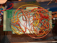
I've never been terribly good at soldering, but I'm definitely getting better at it; practice makes perfect I guess. Although having bought a proper wire stripper I'm amazed just have vital it is! I've always just done it by hand which usually means a long chunk taken off. But with these, I can snip the plastic off a small end of the wire and using a big magnifier, solder it on easily. Its also SO quick to strip a wire, something I just didn't realise! I'd hate to have done this board's wire strippng by hand.
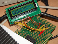 The last image here shows the screen hard at work printing a counter and a welcome message. The code to do this is tiny - and I'll post it later for any who are curious - and extremely easy to use. I may not scrap the board just yet, it may even come in hand for debugging! Printing a row of text will take around 32 scanlines - mainly because I have a fixed delay and have to take into account that I might be in FAST mode. But for debug text...32 lines is okay.
So with this finished, I now need to wait on my SRAM+GAL's (which are finally on its way I think!) and I can look to doing a brand new external RAM card for the Plus/4, or perhaps the MMC card which would be much more interesting I guess. Although...Xeo3 is starting to beg for some attention, so I might dabble a bit in there soon.
All that said... the very 1st thing Im doing next is a board from the expansion bus that can connect to a breadboard. This would have been much easier on a breadboard!
Edit: Okay, code can be found HERE!. Its not terribly exciting, but it completes the project (until I get around to making a circuit diagram that is...)
Sunday, January 07, 2007
Plus/4 LCD addon!!!
 COOL!!! My first proper hardware add on! I've connected up the remaining lines, added some power and wrote a little test program to initilaise it, and then print to it and hay presto! A little LCD screen add-on!
 Of course...Its not that easy. I've missed out a lot of stuff here. For proper full speed access I need to be able to read the busy line which requires READ access. This in turn requires another buffer (I think), and some more logic to detect the READ line and then setting the datalines (at least 1 bit) to be the values it needs to be. All I've done just now is put in some big delays so I know the text will have been set.
Although...after playing a little...it looks like the Plus/4 is so slow.... the delays can more or less be taken out! Which is pretty cool...Still, its not "right", but it does work. I also have no way to reset it properly just now, which means I'd have to add some rest circuitry.
But aside from this...I don't care! It works! Its really easy to write to! And its cool!!!
Subscribe to:
Comments (Atom)